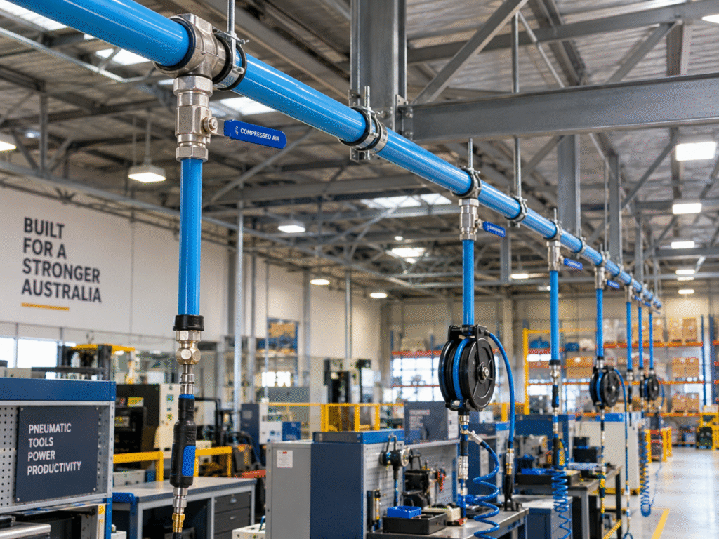
Most facilities don’t think much about their compressed air piping until something goes wrong: a pressure drop at the far end of the line, an unexplained spike in the compressor’s duty cycle, or a leak that’s been hissing away in a ceiling void for months. Yet the piping itself is often where the real inefficiency hides. Studies of industrial compressed air systems routinely find that leaks and poor pipework design account for a significant share of wasted compressor output, sometimes running into thousands of dollars a year in electricity alone for a mid-sized facility. For engineers, plumbers, and facility managers specifying or upgrading a system, getting the piping design right from the outset is one of the highest-leverage decisions in the entire installation.
This article covers what actually matters when planning compressed air piping from layout and sizing through to material choice, fittings, and the maintenance habits that keep a system efficient for years rather than months.
Why Piping Design Matters More Than Most Facilities Realise
It’s tempting to treat compressed air piping as a simple matter of connecting the compressor to the tools that need it, but the layout and sizing decisions made at the design stage have a lasting impact on system performance. Undersized piping creates pressure drop, forcing compressors to work harder and consume more energy to deliver adequate pressure at the point of use. Poorly planned layouts with excessive bends, dead legs, or long straight runs without adequate drainage create both efficiency losses and moisture management problems that compound over time.
The good news is that most of these issues are entirely avoidable with proper planning. A well-designed system accounts for current demand, realistic future expansion, and the practical realities of the facility’s layout, rather than simply replicating whatever pipework happened to be there before.
Loop Systems vs Branch Layouts
One of the earliest decisions in any compressed air piping project is whether to run a ring main (loop) system or a simpler branch layout.
A loop system connects the piping in a closed circuit, allowing air to reach any point in the system from two directions. This reduces pressure drop at the far ends of the network and provides redundancy; if one section needs isolation for maintenance, air can still reach connected tools via the other side of the loop. Loop systems suit larger facilities with multiple points of high demand spread across the floor.
A branch layout, by contrast, runs a single main line with individual branches feeding specific tools or work areas. It’s simpler and cheaper to install, and perfectly adequate for smaller facilities or those with concentrated demand near the compressor. The trade-off is that pressure drop becomes more pronounced toward the ends of longer branches, and any isolation for maintenance affects everything downstream of that point.
Choosing between the two comes down to facility size, layout complexity, and how critical uninterrupted air supply is to daily operations. A food processing line that can’t tolerate downtime has very different requirements to a warehouse running the occasional pneumatic tool.
Sizing the System Correctly
Undersizing is the single most common mistake in compressed air piping projects, and it’s rarely obvious until the system is already installed and underperforming. Proper sizing needs to account for total connected load, the diversity factor (since not every tool runs simultaneously), anticipated future expansion, and total pipe run length, since pressure drop compounds over distance.
A useful discipline is to size the main distribution line generously enough to accommodate planned future growth, even if current demand doesn’t require it; retrofitting undersized mains later is dramatically more disruptive and expensive than installing adequate capacity from day one. Branch lines feeding individual tools can be sized more tightly to actual point-of-use demand, since these are far simpler to modify later if requirements change.
Material Choice: Matching Pipe to the Application
Compressed air piping is available in several materials, each with genuine trade-offs rather than one universally “correct” answer.
- Galvanised or black steel offers strength and heat tolerance but is prone to internal corrosion over time, which can introduce scale and rust into the airline unless properly maintained
- Aluminium provides a corrosion-resistant, lightweight option with a smooth internal bore, though it typically carries a higher material cost than steel
- Poly and composite systems offer fast, tool-free installation and excellent corrosion resistance, making them popular for facilities that expect to reconfigure their layout over time
- Stainless steel is reserved for the most demanding applications: high-purity processes, food and pharmaceutical environments, or highly corrosive atmospheres where its cost premium is justified by hygiene or corrosion requirements
For most general industrial applications, the choice comes down to balancing installation cost, expected system lifespan, and how frequently the layout is likely to change. A well-specified compressed air piping system should match material to the actual operating environment rather than defaulting to whatever was used in the facility previously, particularly if that previous system underperformed.
Fittings, Drainage, and Leak Prevention
The pipe itself is only half the system; compressed air pipe and fittings need to be selected as a coordinated set rather than assembled from whatever happens to be compatible on paper. Mixing fitting brands or thread standards is a common source of slow leaks that go undetected for extended periods, quietly draining compressor efficiency the entire time.
Drainage deserves particular attention. Compressed air always carries some moisture, and lines should be designed with a slight fall toward drain points rather than running dead level, allowing condensate to move away from tool connections instead of pooling at low points in the system. Automatic drain valves at low points reduce the manual maintenance burden considerably compared to relying on staff to manually bleed condensate on a schedule that’s easy to forget.
Leak management is an ongoing discipline rather than a one-off installation task. Regular ultrasonic leak surveys, particularly in older facilities, routinely uncover leaks that individually seem minor but collectively represent a meaningful drain on compressor capacity and electricity costs. Building a periodic leak-check routine into general maintenance schedules pays for itself many times over across the life of the system.
Planning for Future Expansion
Facilities rarely stay static, and compressed air demand tends to grow as equipment is added or processes change. Designing a system with isolation valves at logical branch points allows future work to be carried out without shutting down the entire facility’s air supply a detail that’s easy to skip at initial installation but becomes enormously valuable the first time a section needs isolating for a modification or repair.
Leaving accessible capacity in main distribution lines, along with clear documentation of the system layout, run lengths, and connection points, makes future expansion considerably less disruptive than starting from an undocumented, tightly sized system with no spare capacity.
Final Thoughts
Compressed air piping rarely gets the design attention it deserves, given how directly it affects both energy costs and operational reliability across a facility’s lifetime. Getting the layout, sizing, material choice, and fittings right at the planning stage rather than accepting whatever configuration happens to already exist is what separates a system that runs efficiently for decades from one that quietly drains money through pressure drop and leaks. For engineers and plumbers planning their next installation or upgrade, treating compressed air piping as a genuine design exercise, rather than an afterthought bolted onto the compressor selection, is the habit that pays off longest.